Closed-loop adaptive optical system for laser beam control
Abstract
This paper discusses the novel adaptive optical closed loop system with bimorph mirror as a wavefront corrector and Shack-Hartmann wavefront sensor to compensate for the aberrations of the laser beam occurred during the distribution of the beam from laser to processed material. Adaptive system can correct for the low-order aberrations in the real-time - the frequency of corrected aberrations is less then 25 (30) Hz. The amplitude of such aberrations - about 7 microns. These parameters are mostly determined by utilized Shack-Hartmann wavefront sensor. Number of corrected aberrations - up to 15th Zernike polynomial (excluding tip-tilt).
Keywords: active corrector, wavefront sensor, laser beam control.
1. Introduction
Adaptive optical systems are used to be applied to
control for the aberrations in astronomy - the aberrations of the light from the
stars that passed through atmospheric turbulence. Such systems had to
compensate rapidly changing high order aberrations to improve the vision of the
objects, in fact, not always the astronomical ones1. They were
rather expensive (up to 2-3 million USD), large, and of course could not be
used for commercial application in lasers and laser complexes. But the
development of contemporary adaptive optics technique allowed nowadays to
believe that such systems could be used in various apparatus, including lasers.
In our Group we managed to design first commercially available adaptive optical
system for laser beam control. As usually, such system consists of wavefront
corrector - in our case, bimorph deformable mirror, wavefront sensor -
Shack-Hartmann type of sensor, control unit and software worked out in our
Group.
In next chapters we shall consider all these main elements of adaptive system and will present the result of the work of the whole system to control for laser beam.
The main element of any adaptive optical system, the element that determines the properties of the whole system is wavefront corrector. In our work we suggested to use the semipassive bimorph mirror to compensate for the aberrations of the laser beam2. The advantages of the use of such mirrors in adaptive system are: continues deformation for the mirror surface (no diffraction losses on the edges of controlled subapertures), large deformation of the surface (up to 30 microns), wide dynamic range (up to several kHz), ability to hold high radiation loading (up to 3 kW CW per cm2) and one of the most important features - the possibility to correct for the low-order aberrations by minimal number of controlled elements (channels). These properties of bimorph mirrors make nowadays them one of the most widely used correctors not only in laser beam control but also in astronomical and medical applications of adaptive optics.
Fig.1. Scheme of a semipassive bimorph corrector
Fig.2. Various schemes of the control electrodes on the surface of the piezodisk
The traditional semipassive bimorph mirror consists of a glass, copper or quartz substrate firmly glued to a plate actuator disk made from piezoelectric ceramic (lead zirconium titanate, PZT) (see Fig. 1). Applying the electrical signal to the electrodes of the piezoceramic plate causes, for example, tension of the piezodisc. Glued substrate prevents this tension, and this result in the deformation of the reflective surface. To reproduce different types of aberrations with the help of such corrector the outer electrode is divided in several controlling electrodes, that have the shape of a part of a sector. The size as well as the number of such electrodes depends upon the number and the type of the aberrations to be corrected. In our work we usually used the geometry of the electrodes given on Fig. 2. The behavior of the bimorph corrector (deformation of the surface when the voltage is applied to the particular electrode) is well described by the following equation3:
 ;
;
 ;
;
 ;
;
Here, h1, h2 - the thickness of
a piezodisk, and substrate, E1, E2 - Young's modulus of a
piezodisk and substrate, h - total thickness of the mirror, ν - the Poisson ratios, d31
- transverse piezo modulus,  - the strength of the electric
field applied uniformly to the given electrode. This equation was used to
optimize radii r1 and r2 (Fig. 2) for the best correction
of the low order aberrations such as coma, astigmatism, spherical aberration.
- the strength of the electric
field applied uniformly to the given electrode. This equation was used to
optimize radii r1 and r2 (Fig. 2) for the best correction
of the low order aberrations such as coma, astigmatism, spherical aberration.
Several types of the bimorph correctors were produced in Adaptive Optics Group in IPLIT Russian Academy of Sciences. The technology of fabrication of such a corrector was the following: semipassive bimorph plate was heated in a furnace for 4 - 5 h at 80°C until the glue had completely hardened. The plate was then cooled in a refrigerator to remove any residual thermal deformations before being reheated in the furnace. This procedure was repeated four or five times. The quartz substrate was then polished to obtain an optical-quality surface (the deviation from sphere should not be greater then 0.1 μ) before a high reflectivity dielectric of metal coating (up to 99.98%) was deposited on its surface. Conductors were then glued to the common and controlled electrodes. The corrector was inserted in a mounting at the back of which there was a connection to the control voltages. The main features of a semipassive bimorph corrector are shown in Table 1.
| Working aperture | 40, 50 mm |
|---|---|
| Thickness of the mirror | 3 - 5 mm |
| Number of actuators | 8, 13, 18 |
| Mirror quality | 0.2 μ (P-V) |
| Stroke | 7 - 15 μ |
| First resonance | 2 - 7 kHz |
| Substrate material | Glass, quartz, copper |
The static and dynamic characteristics of the mirrors were studied by an interference method. We used Zygo Mark-3 phase-shifting interferometer. The sensitivity of correctors was estimated from the displacement of the interference fringes at the center of the pattern when the voltage of 100 V was applied to all electrodes. The frequency of the first resonance of our correctors was in the range of 3 - 5 kHz. Table 2 presents the measured RMS errors of approximation of some low-order aberrations by 17-electrode bimorph corrector.
| Type of aberration | RMS error |
|---|---|
| Defocus | 0.1 % |
| Astigmatism | 0.2 % |
| Coma | 3.0 % |
| Spherical aberration | 5.3 % |
For high average power lasers there is the problem of constructing controllable cooled mirrors, production of which is rather complicated. A corrector of this kind should satisfy a number of technical requirements: it should have the necessary optical strength, its service life should be long (~ 1000 hours), and it should be easy to construct and use.
In our Group we have developed water-cooled mirrors based on semi-passive bimorph piezoelement. They consisted of a copper (or molybdenum) plate 2.5 mm thick and 100 mm in diameter. One side of the plate was polished and used as a mirror, whereas two piezoelectric ceramic disks 0.3 mm thick and 50 and 46 mm in diameter were glued on the other side. First piezodisk was used to control for the curvature of the mirror surface and 17 electrodes were evaporated on the outer side of the second piezodisk to compensate for different aberrations of the wavefront. The cooling system of the corrector was of the waffle type. A copper plate consisted of two soldered disks in which channels of 0.5 mm deep were formed for the circulation of the cooling liquid. The size of the contact areas between the plates was 3x3 mm. Fig. 3 shows the sample of such a corrector. An active mirror was tested under an optical load of CO2 laser radiation with an average power density of 2.5 kW/cm2 4. The corrector surface profile was determined using a shearing interferometer. This optical load produced practically no deformation of the mirror surface, indicating that the cooling system was effective. The rate of flow of cooling water was 400 mliter/min. There were no distortions of corrector response function under the action of this load. A similar test of an uncooled adaptive mirror resulted in considerable thermal deformation of the surface.
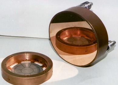
Fig.3. Scheme of a semipassive bimorph corrector
These bimorph correctors were successfully used to control for the radiation of an industrial lasers.
3. Shack-Hartmann wavefront sensor
One of the demands of any industrial focused system - is its reliability and ability to work not only in laboratory, but also in the real conditions of the factory, plant etc. From this point of view Shack-Hartmann wavefront sensor is the most suitable one to be included as a part of AO system for industrial needs5. These kinds of sensors are widely used by astronomers or in medical research but in fact never were applied to control for laser beam.
4. System design and results
Elaborated control unit allowed to apply the voltages in the range of -270 - +270 Volts with the frequency up to 100 Hz to all 18 channels of active corrector. The control of this unit was driven through PC. Software was designed for Win'98.
Fig. 4. presents the scheme of the experimental setup we used to test the work of the closed loop adaptive system.
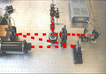
Fig.4. Closed-loop adaptive optical system - experimental setup
In our system two deformable mirrors were used - one mirror to introduce various aberrations of the wavefront (that mirror was controlled manually) and second mirror - of compensate for the aberrations of the wavefront. To calibrate Shack-Hartmann sensor two beamsplitters were introduced to direct the radiation of the laser beam on sensor to avoid the reflection of the beam from active correctors. In order to verify the efficiency of active correction of the laser beam laser beam analyser was introduced into this system to evaluate the focal spot of the beam.
To control for the wavefront we used the algorithm presented on Fig. 5.
Fig.5. Algorithm of closed-loop adaptive control
On the first stage the software is testing the existence of the elements of the whole adaptive system - framefrabber, control unit and the number of output channels.
On the second stage the calibration of the sensor is carried out - the reference picture is stored in computer memory and some preliminary calculations are made.
On the third stage system is determining the response functions of the electrodes of bimorph corrector (second mirror, Fig. 4) applying 100 V consistently to all electrodes and grabbing the correspondent Shack-Hartmann pictures to computer memory.
After the preparation work was completed the WORK REGIME starts. We applied some voltage to first deformable mirror and introduce wavefront distortions into the laser beam. This wavefront is measured by SHW. Then the voltages to be applied to all electrodes of the bimorph mirror are calculated. And these voltages multiplied by coefficient 0.9 are applied to electrodes of our corrector - second deformable mirror. In this case the wavefront is not absolutely compensated and the residual distortions are measured by SHW. Again voltages to be applied to corrector electrodes are calculated and applied with coefficient 0.9. And so on. The coefficient 0.9 a bit slows down the work of the whole system but improved the stability of the whole system.
Fig. 6. demonstrates the intensity distribution measured by Laser Beam Analyser in the focal plane of lens before correction and after two steps of correction. The focal spot of the corrected beam is about 1.7 times larger then the diffraction limited one due to existing aberrations in the optical path that could not be compensated by 18-element bimorph mirror. Though from the pictures it could be seeing that the overall size of the focal spot decreases by 3 times.
Fig.6. The intensity distribution in the focal plane of lens before correction and after two steps of correction
Acknowledgements
This work was supported by NATO "Science for Peace" programme grants N 974116 and 974292.
References
- C.Paterson, I. Munro, J.C. Dainty, "A low cost adaptive optics system using a membrane mirror", Opt. Express 6, pp. 175-185, 2000
- J.C.Dainty, A.V.Koryabin, A.V.Kudryashov, "Low-order adaptive deformable mirror", Appl. Opt. 37(21), pp. 4663-4668, 1998.
- A.V.Kudryashov, V.I.Shaml'hausen, "Semipassive bimorph flexible mirrors for atmospheric adaptive optics applications", Opt. Eng. 35(11), pp. 3064-3073, 1996.
- Laser Resonators: novel design and development. Alexis Kudryashov, Horst Weber, editors, SPIE Press, p.301, 1999.
- Adaptive Optics Associates Inc., http://www.adaptiveoptics.com.
Return to Night N (opt) Ltd Scientific Activity page